Arc Risk on the DC Side and the Cable Behind It
A DC arc does not stop by itself. Alternating current crosses zero a hundred times a second and the arc goes out; direct current has no such moment, so a small series gap can keep drawing a flame until something melts. The cable carrying that current is part of the chain, and the published figures for KUKA CABLE run from a 10 kV spark test in production to a 6.5 kV AC pressure test on every finished drum.
Key takeaways
- A DC arc persists where an AC arc self-extinguishes, which is why DC faults are often found only after heat has spread.
- The maker lists a spark test at 10 kV during production and a 6.5 kV AC test for five minutes on finished cable.
- Ambient rating is −40 °C to +90 °C, with short-circuit values of +120 °C for 20,000 hours and +250 °C for five seconds.
- The published flame test exposes a single cable to 800 °C for one minute and expects it to stop burning on its own.
Two kinds of DC fault, one cable
A series arc starts inside the conductor path: a poor crimp, a loosened screw terminal, a strand broken by repeated bending. The gap is millimetres wide and the current is the normal string current, so nothing upstream notices. A parallel arc starts between conductors, or between a conductor and a grounded frame, after insulation has been cut, crushed or eaten away by sunlight. In both cases the cable is either the path or the barrier.
That is the reason to look at construction rather than only at current rating. A tinned-copper conductor resists the corrosion that slowly raises joint resistance, and a cross-linked insulation layer resists the cracking that opens a parallel path. Once either process starts, the heat it generates is fed by the array itself, at whatever the string produces on a clear day.
What is tested before the drum ships
The 1500 V product page lists the checks applied to this solar dc cable. A spark test at 10 kV runs during production, so pinholes in the insulation are caught on the line rather than on a roof. The finished cable then takes 6.5 kV AC at 50 Hz for five minutes, which is far above the rated DC 1.8/1.8 kV the cable sees in service.
- Rated voltage: DC 1.8/1.8 kV.
- Spark test during production: 10 kV.
- Pressure test on finished cable: 6.5 kV AC, 50 Hz, five minutes.
- Bending radius: four times the outer diameter.
The same page describes insulation and sheath as XLPO, electron-beam cross-linked and LSHF, and lists the design against TUV 2PfG 1169/08.2007, EN 50618:2014 and IEC 62930. Halogen-free compounds matter in a fault, because the smoke they release is less corrosive to the metal parts around them than the smoke from a halogenated sheath.
Fire and water around a fault
The client highlights two regional requirements in the same section of its site: a CPR fire rating and an AD8 waterproofing rating. Those are the ratings a specifier is asked to confirm on European projects, and they sit alongside the vertical flame test described for PV cables, where a single cable is exposed to burning at 800 °C for one minute and is expected to self-extinguish.
Water is not the opposite of fire risk; it is a second route to the same result. Moisture in a damaged sheath lowers insulation resistance, leakage raises local temperature, and the temperature finishes what the nick started. The lab keeps a water resistance test on its published list for exactly that reason, and the maker's stated service expectation for these cables is 25 years or more.
Diameter, clipping and the bend that starts trouble
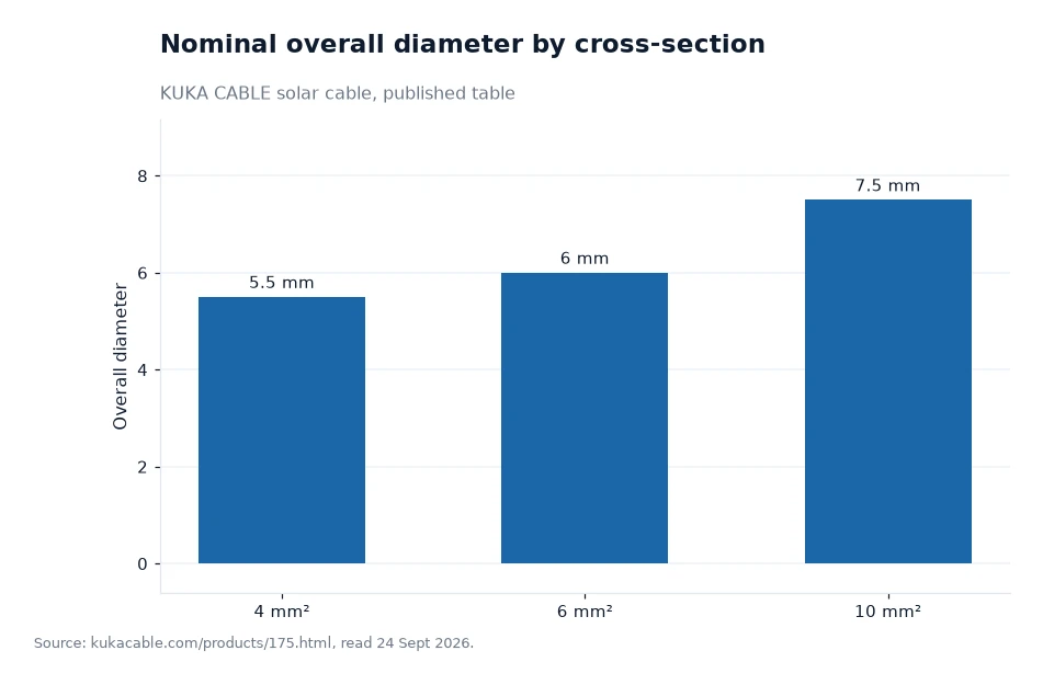
Conductor size decides how much room a fault path has. On the published cross-section table, the three common sizes measure 5.5 mm, 6.0 mm and 7.5 mm across, with a nominal weight of 59 g/m, 78 g/m and 130 g/m. Multiply the diameter by the published bend rule of four times and the minimum radii work out at roughly 22 mm, 24 mm and 30 mm — my own arithmetic on two printed figures, offered as a working guide rather than as a published value.
That matters to fault prevention because a cable squeezed below its bend limit holds internal strain. The sheath thins at the outside of the bend, the insulation follows, and a few seasons of thermal cycling turn a tight clip into a crack. Clip spacing and corner geometry are worth as much attention as the drum label.
Published cross-section figures
| Cross-section | Nominal overall diameter | Minimum bend radius (author's calculation) | Nominal weight |
|---|---|---|---|
| 4 mm² | 5.5 mm | 22 mm | 59 g/m |
| 6 mm² | 6.0 mm | 24 mm | 78 g/m |
| 10 mm² | 7.5 mm | 30 mm | 130 g/m |
| 16 mm² | 8.8 mm | 35 mm | 190 g/m |
| 25 mm² | 11.0 mm | 44 mm | 292 g/m |
Worked example
Take a 10 mm² string run and a corner drawn 25 mm tight. The published rule sets the floor at four times 7.5 mm, which is 30 mm by my multiplication, so the drawn corner is 5 mm under the limit before any pull tension is added. On a 4 mm² run of 5.5 mm diameter, the same rule gives 22 mm, which is why the smaller cable tolerates tighter corners on the same roof.
The difference between the largest and smallest of those three sizes is only 2 mm of diameter, 7.5 mm against 5.5 mm, yet the bend floor moves by 8 mm once the factor of four is applied. That arithmetic is mine, and it is the reason two cables of the same family cannot share one clipping plan without checking.
Frequently asked questions
Why is a DC arc more dangerous than an AC arc on a PV array?
Direct current has no zero crossing, so the arc has no natural moment to die. A series fault draws the normal string current through a tiny gap and can burn for as long as the array is lit, which is why a thermally damaged joint may be the first visible sign. The published cable figures to hold a supplier to are the 10 kV spark test, the 6.5 kV AC five-minute test and the +250 °C five-second short-circuit limit.
How much can this cable be bent before the insulation is stressed?
The published limit is a radius of four times the outer diameter: about 22 mm for a 4 mm² cable, 24 mm for a 6 mm² and 30 mm for a 10 mm², all by my own multiplication of the printed diameters. Keep the first bend clear of the connector by a hand's width, and check that the corner radius on the drawing is larger than the cable's published floor before clipping begins.
What to put in the specification
Name the rated voltage, the insulation compound and the fire and water ratings you need, then ask for the type-test reports behind them. The manufacturer's site does not publish connector torque values, contact resistance or the arc-fault hardware that may sit elsewhere in the system, so those items have to be requested from the supplier rather than read from the product page. If the project crosses a coastal or high-humidity site, treat the AD8 rating and the water resistance test as part of the same question as the arc risk, because one leads to the other. The 1500 V solar cable page carries the electrical and mechanical list, and the laboratory test pages show how each value is checked.
Diameter, weight and test values behind this arc-risk piece are the manufacturer's own website data, read by me there on 24 Sept 2026[1].